uPlan Work area
uPlan’s main window consists of the following areas:
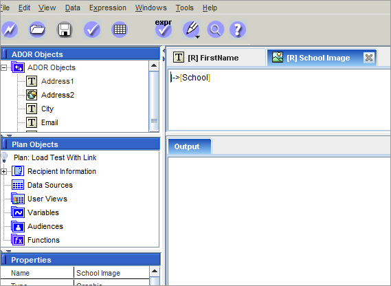
ADOR Objects
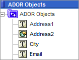
ADORs are plan objects that are visible to a Design (via the “Link to Plan” operation of uCreate). ADORs can be of various design-centric types, for example, text, graphic, etc. The designer uses simple point-and-click operations to tag a design object (say, a text frame or graphic frame) with the desired ADOR. Such a tagged design object becomes a Dynamic Object: a design object that derives its content and/or appearance from the ADOR’s value.
ADOR values are calculated by the plan’s rules, using the given data source(s). These calculations are performed iteratively, once for each recipient, resulting in a set of recipient-specific values for each ADOR. In a way, one can think of ADORs as the intermediaries between the logic (that is, plan) and data (that is, data source) and the Design (that is, XMPie tagged document).
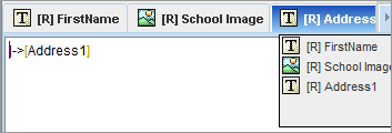
Each ADOR is defined by an expression, which specifies how to calculate that ADOR’s value as a function of the customer profile or information in the database. Double-clicking an ADOR displays its expression in the Expression tab. You can then edit the displayed expression using XMPie’s proprietary QLingo language, SQL, or both.
Plan Objects
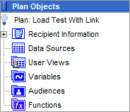
uPlan displays plan Objects in a hierarchical tree structure, consisting of the following:
|
Option |
Description |
|---|---|
|
Recipient Information |
Represents the structure (schema) of the Recipient List and the filters that enable you to specify which recipients are being targeted by this campaign.
|
|
Data Sources |
Describes the data source structure that is expected by the logic. The data schema consists of the following objects (displayed in a hierarchical tree structure):
The data schema also defines the relationship between these tables, for example: a common field. You can either import the data source schemas using the uPlan Wizard (see Creating a Plan using the uPlan Wizard), or add them manually when you create a new blank plan (see Creating a Blank Plan). For further details, see Working with Data Sources. |
|
User Views |
Represent views of a database that can be created and edited. User-defined views are useful for defining Table ADORs. They are also useful for creating a temporary structure that holds the results of complex database operations, such as joins or other calculations. For further details, see Defining User Views. |
|
Variables |
Internal plan objects, which can be assigned values of expressions (QLingo, SQL, etc.). A variable can also be used as input for expressions that compute values of ADORs. Variables allow for avoiding repeat computations or data retrievals, as well as improved readability of the plan, for later revisions, etc. Note that variables are not visible to uCreate (hence to the designer). For further details, see Working with Plan Variables. |
|
Audiences |
Represents target audiences, broken down into segments. Each segment represents a group of recipients to which you can apply rules. For further details, see Defining Audiences. |
|
Functions |
Lists user-defined functions that perform operations on retrieved data to define plan objects or variables. This enables you to define functions that perform manipulations on retrieved data and use the output value for display or further manipulation. A standard library of QLingo functions and other constructs is available from the Expression > QLingo Templates menu. For further details, see Working with Plan Functions. |
Properties Pane
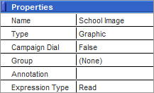
The Properties pane is used to view and edit the attributes of the object selected in the ADOR Objects pane or Plan Objects pane.
Some properties are common to most objects, for example: Name and Annotation. Other properties are specific to the type of object you have selected, for example: ADORs and variables have Type and Campaign Dial properties, while data sources have a Database Link property.
Expression Tabs Pane
The Expression Tabs pane allows you to easily view and edit QLingo or SQL expressions. When you open an expression, its tab is added to the Expression Tabs pane.
To display an expression tab:
Expression tabs can be displayed in any of the following ways:
-
Double-click the relevant ADOR or plan Object.
-
If this expression has not been opened yet, its tab is added to the Expression Tabs pane.
-
If this expression has already been opened, its tab is selected in the Expression Tabs pane.
-
-
The Windows menu lists all currently open expressions, allowing you to conveniently focus on the desired expression by clicking its name.
If the Expression Tabs pane
is not large enough to display additional expressions, any new expression
tab you open takes the place of another expression tab.
In this case, an arrow is displayed at the upper-right corner of the application
![]() . Clicking this arrow displays a list of all open
Expression windows, with the hidden tabs
indicated in bold font.
. Clicking this arrow displays a list of all open
Expression windows, with the hidden tabs
indicated in bold font.
You can conveniently move between the open expression tabs using the <Ctrl> + <E> keyboard shortcut.
Output/Search Results Pane
The Output tab displays summary messages, warnings and error messages concerning the operations performed in uPlan. This output does not require a direct response; its purpose is to allow you to keep track of operations such as validation, proof set generation and data source generation.
When a message in the Output tab concerns an expression or an object (an ADOR or a plan Object), double clicking the message opens the relevant expression in the Expression Tabs pane, or highlights the object in the ADOR Objects or Plan Objects tree.
If the output is a message specifying the exact location of the error or the warning (that is, the line number and character number), double-clicking this message displays the relevant expression in the Expression Tabs pane, with the cursor indicating the location of the error or warning.
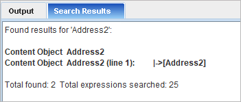
The Search Results tab displays results of a search (for ADORs, variables, functions, filters , audiences, user views, schemas and data sources). Clicking a result opens the relevant object.
Customizing the uPlan Workspace
When working with uPlan, you can define various options and preferences for your convenience:
-
Warnings: receive a warning before an object is deleted. To toggle this option, select Edit > Preferences. In the Preferences dialog box that is displayed, select or deselect Warn before Deleting Objects.
-
Toolbar display: view or hide the toolbar. To toggle between viewing and hiding the toolbar, select View > Toolbar.
-
ADOR display: list all the plan objects as one tree, or view the ADORs in a separate tree. To toggle between viewing the plan objects as one tree, select View > Objects as One Tree.
-
uImage Defaults: set the uImage Default Folders so that uImage can append file names to the default folders.
Setting uImage Default Folders
When producing output that contains personalized images, you are required to specify the paths of uImage-related folders: the uImage Template, the Output Folder and the Assets Folder. These paths may be either absolute or relative:
-
If absolute paths are used, then switching between computers (for example, to allow different designers to work on the same uImage Template) requires manually recreating the same paths on each computer to allow uImage to function properly.
-
If relative paths are used, switching between computers does not require any manual adjustments. Instead, uImage automatically calculates the correct location of the files according to the locally-defined default folders. The relative paths are relative to the uImage Default Folders.
The uImage Default Folders are set in uPlan’s Preferences dialog. There are default folders for each type of file: the uImage Template, the personalized output files and the Assets used to personalize these files.
uImage appends the relative path to the relevant default folder. For example, if a relative path, such as myImages\test.psd, is given, then myImages folder is assumed to be in the Templates default folder (note that if an absolute path, such as C:\myImages\test.psd, is used, the image is retrieved directly from the indicated path, without considering the default settings).